Converter design
The state of the steelmaking process makes it almost impossible to directly observe everything that happens in the converter. At present, there is no mathematical model that can fully describe the high-temperature metallurgical and fluid dynamic processes. Since the birth of converter steelmaking, it has been continuously studied and improved, so the metallurgical reactions are more fully understood. However, the following two examples clearly show that there is still a lot of research to be done.
The position of the stirring tuyere at the bottom of the furnace still needs to be optimized. These tuyere provide a better stirring effect on the molten steel, reduce the carbon content more quickly, and should shorten the smelting cycle. However, today the optimal position and number of tuyere are based on experience. Someone abroad conducted research in this area in 2000 and soon found that the description of high-temperature fluid dynamic processes is very complex and can only be feasible with many assumptions. For example, the bubbles and their reaction with the molten steel can only be described approximately.
The mathematical description of the converter swing during blowing still needs to be elaborated in detail, especially those bottom-blowing or side-blowing processes, whose shaking is very violent. These vibrations are caused by spontaneous processes. The energy introduced during the oxygen blowing process causes the system to oscillate at a very low Eigens frequency, usually 0.5 to 2.0 Hz. The discovery of mathematical models that can describe this nonlinear chemical and mechanical fluid dynamic system has not yet been completed.
Converter shell
In the mechanical part of the converter, the steel is contained in the shell lined with refractory materials, which exhibit complex nonlinear thermo-viscous elastic-plastic behavior and nonlinear contact with the steel shell. The behavior of the steel shell itself is more or less understood, and it is possible to describe this temperature-dependent elastic-plastic material and its creep effects. However, there are still many unknowns about the interaction between the steel shell and the refractory materials. Converter design is more of an art than a science, but experience, material improvements and the application of computational techniques are helping to better understand and design this mechanism.
↑There are several criteria for optimizing the shell design. The most important one is the volume of the interior surrounded by the refractory materials. In order to have the largest reaction space and achieve the best metallurgical process, this volume should be maximized within the available space. The ratio of reaction space to steel mass is used for comparison, which is generally 1.0 m3/t. However, the constant pursuit of increasing the productivity of steelmaking equipment with the lowest investment has led to steel mills increasing the loading while keeping the original shell unchanged, which has reduced this ratio. The consequence is severe splashing, which tends to occur when the furnace volume ratio drops to 0.7-0.8 m3/t. Today, the shape of the converter body, i.e. the upper and lower cone angles, the diameter-to-height ratio, etc., is determined by the steelmaker or by the existing equipment, the flue gas system, the height of the tilting axis, the tilting drive, etc. Therefore, when designing a new furnace, only a few parameters can be changed.
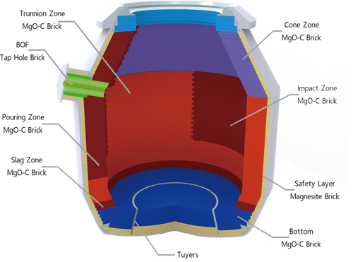
↑The modern converter consists of an upper cone with a furnace head iron ring, a barrel-shaped furnace body and a lower cone with a dished bottom. In recent years, the joint components between the upper and lower cones and the furnace body, and between the lower cone and the furnace bottom have been removed. Production experience shows that the stress in these areas is not as severe as originally imagined, and can be solved by using high-quality furnace shell materials, so the above approach is feasible.
Furnace Shell Design Criteria
An important step in the design process is the shell process verification, that is, the calculation of stress and deformation and comparison with the allowed limit values. Metallurgical vessels such as converters do not need to meet specific standards for their design. In the evolution of the art of converter design, the initial shell design referred to the design standards of boilers and pressure vessels. The successful commissioning of products designed in accordance with this design shows that these standards are also applicable to steelmaking production practices. However, the converter is not a pressure vessel after all. Its internal pressure comes from the thermal expansion of the refractory material, not the liquid or gas in the boiler. Moreover, damage such as cracks will not cause an explosion like a high-pressure vessel. This is why the design of the converter does not fully follow the design standards of pressure vessels.
Furnace shell thickness
The selection of the wall thickness of traditional pressure vessels is mainly based on the internal pressure. However, in the converter, this pressure cannot be accurately calculated. It is determined by the interaction between the refractory material and the furnace shell and the production operation. When determining the thickness of the furnace shell, other load factors must also be taken into account, mainly including: mechanical loads caused by the weight of equipment, refractory materials and molten steel; internal pressure generated by the interaction between the furnace shell and the refractory lining, that is, secondary pressure; mechanical loads caused by external forces, such as dynamic mass effect, adding molten iron, adding scrap steel, and tapping; temperature and temperature gradient on the furnace shell; deformation of the furnace shell under the action of temperature, causing mechanical loads on the suspension system; secondary stresses in the furnace shell due to uneven temperature distribution of the furnace shell and the suspension system.
AISE’s 32nd Subcommittee once tried to give a simple recipe program to calculate the thickness of the furnace shell. However, some studies have shown that it is impossible to define a simple program or criterion for determining the thickness of the furnace shell. These criteria can be used to determine the furnace shell on the basis of proven results. However, the introduced forces, such as those from the suspension system, must be calculated in detail using the finite element method. The suspension system developed abroad is statically determinate, so all loads within the system can be calculated accurately. The advantage of this feature is that local stresses and deformations can be calculated very accurately.
Converter life
World experience shows that the converter life is limited due to long-term deformation. The converter reaches the end when the shell hits the support ring, usually 20-25 years. This deformation is caused by creep. Creep is a typical behavior of materials in high temperature environments (>350°C). Creep deformation is related to temperature, stress level and the materials used. There are only a limited number of possible ways to extend the converter life, such as cooling the shell, material selection and production operations.
Cooling system
In principle, forced cooling of equipment is not absolutely necessary, and natural ventilation cooling is sufficient. Many practical applications have proved this. However, forced cooling reduces the equipment temperature and has a positive effect on reducing creep deformation, thereby extending the life of refractory materials and ensuring higher yield strength at production temperatures. Some steel mills apply cooling systems to converter shells, such as water cooling, forced ventilation, compound gas-water cooling (mist cooling), etc. The most effective cooling method is water cooling.
Material selection
Initially, the furnace shell material mainly used high temperature resistant pressure vessel steel. In order to withstand many unknown loads and stresses, fine grain steel is particularly preferred. This kind of steel has a relatively low yield strength, but has a relatively high strain hardening capacity above the yield point. Its advantage is that when overload occurs, there will be enough excess strength, and even when cracks appear, brittle crack propagation will not occur. The cracks will either stop developing or grow at a very slow rate. The steel used for the furnace shell is generally A516Cr60, Aldur41, Altherm41, Wste285, Wste355, P275NH, P355NH, etc.
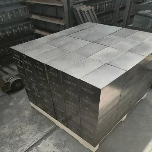
This principle is still valid for new converters, but in the last 10-15 years, the life of the furnace lining has been extended due to the use of magnesia carbon bricks and slag splashing furnace protection technology. These changes have led to an increase in the furnace shell temperature, which has promoted the creep effect and shortened the life of the furnace shell. In order to offset the creep effect, more creep-resistant materials have been selected, such as A204Cr60, 16Mo3, A387Cr11, A387Cr22, 13CrMo44, etc. The disadvantage is that these steels have ordinary grain sizes and are difficult to weld.
The suspension system is an important part of the converter. An ideal suspension system should not affect the behavior of the shell and should be maintenance-free during production. Many different converter suspension systems have been developed over the years. Initially, the support ring was integral to the converter, but it soon became separate. The principles of the various suspension systems are different, for example, the Japanese use a rigid system, as opposed to the free converter. The rigid support ring suppresses the deformation of the shell, but any restraint on thermal expansion will produce very high stresses, increasing the chances of cracks in the shell.
To allow the converter to expand or deform, and the support ring cannot create additional stress, this requires the suspension system to be designed to be statically determinate. Based on this principle, VAI has developed a series of converter suspension systems, such as bracket systems, VAI-CONDisk, VAI-CONLink, VAI-CONQuick, etc. VAI-CONLink is a maintenance-free suspension system, and its design has received good application feedback. A typical application is the 160t converter of Paulista Ferrous Metallurgy Company in Brazil. Its size parameters are: molten steel measurement 160t, volume 160m3, furnace volume ratio 1.0m3/t, converter height 8920mm, furnace shell thickness 70mm, bottom cone thickness 55mm, dish bottom thickness 55mm, converter outer diameter 7300mm. The shell is made of Mo alloy steel 16Mo3 (equivalent to ASTMA 204Gr.B). The support ring adopts a box-section welded structure with a gap of 250mm between the shell and the furnace body so that it can be assembled with the air cooling plate of the furnace body. The upper cone is equipped with a well-proven water cooling system. These two cooling systems are mainly used to extend the life of the refractory lining and also cool the shell. The converter adopts the VAI-CONLINK suspension system. For metallurgical reasons, the shell is equipped with 6 bottom stirring tuyere.
Converter Technology
Along with converter design, modern advanced converter technology includes:
Bottom stirring and low slag operation using inert gas improve metallurgical processes;
A large amount of secondary metallurgy is incorporated into converter technology;
Computer process automation and related sensor technology improve quality, production efficiency, production safety, and reduce production costs.
Tools, equipment for smooth equipment operation, easy maintenance, and refractory materials with extended life;
Systems to improve the environmental compatibility of waste.
The goal of further development of converter technology is to improve the economic efficiency of the process, that is, to optimize logistics and equipment operation, and optimize process technology. The optimization of process technology is not simply limited to target analysis, determination of target temperature and selection of additive materials, but also includes production operations, such as the position of the oxygen lance and the blowing mode, the immersion time and depth of the auxiliary lance, the addition mode of the addition system, the stirring mode of the furnace bottom stirring system, etc. All of these must be standardized before the equipment is put into production and optimized for the steel grade produced during the commissioning.
Dynamic process control requires auxiliary lance system and vent gas analysis. The auxiliary lance system measures temperature, carbon content and molten pool liquid level position and takes samples during the steelmaking process. Therefore, it is possible to achieve timely measurement during blowing without losing production time. The auxiliary lance system is fully automated and the measuring probe can be replaced within 90 seconds. The development in the field of process automation in recent years is the use of the Dynacon system to achieve complete dynamic control. The system realizes steelmaking process control from the start of blowing to the end of blowing through continuous gas analysis.
↑The function of the slag stopper is to reduce the slag carryover of the ladle. The slag stopper operation reduces the consumption of deoxidizing materials, especially when producing low-carbon steel grades. Another feature is that the ladle slag desulfurization is required in secondary metallurgy, and the slag stopper operation can also reduce the amount of ladle slag additives. At the same time, the slag removal operation and temperature loss of the ladle are also avoided. The ladle slag required for secondary metallurgy is thus formed during the converter tapping process.
According to experience, when the slag stopper is not used, the slag carryover during tapping is 10-14 kg/t steel. After the slag stopper is used, the slag carryover is reduced to 3-5 kg/t steel. Used in conjunction with the slag sensor, the slag carryover can be stably controlled within the range of 2-3 kg/t steel. Another advantage is that it reduces the phosphorus content from about 30 ppm to 10 ppm. Therefore, the number of heats with unqualified phosphorus content is reduced.
In view of the improved metallurgical effect of bottom-blown converters, such as OBM/Q-BOP, K-OBM, etc., it was decided to develop the bottom inert gas stirring technology for top-blown converters. The system should take advantage of the bottom blowing and avoid the disadvantage of replacing the bottom in the middle of the furnace service. Taking the third converter plant of Voestalpine as an example, under the condition of 1650℃ without stirring, the carbon content at the end of blowing was 0.035%, and the average value of [C]×ao was 0.0033. When the bottom blowing stirring with a ton steel flow rate of 0.08Nm3/min was adopted, this value was reduced to 0.0023. If the bottom blowing stirring is not adopted, there will be about 1% iron loss and the lime consumption will increase by about 25%. Assuming that the slag carrying capacity in the ladle is 12kg/t steel (without slag blocking), the aluminum consumption per ton steel will increase by 0.7kg. Moreover, the larger the corresponding converter slag volume, the more refractory materials can be consumed. In a BOF converter without bottom blowing and stirring, it is not economical to reach a carbon content of 0.035% at the end of blowing, and the carbon content is generally limited to 0.045% to 0.050%.
Logistics optimization and routing algorithms are designed specifically for the layout of steel plants and production equipment to find the best configuration. The user-friendly interface and standardized output make it a very useful tool that can optimize and simulate the configuration of any steel plant, allowing users to test a variety of different layouts and process options. It enables users to find the best solution in terms of production time management, maintenance, and auxiliary equipment capacity.
In order to determine the most economical production method for different steel grades and the use of different production equipment, long-term experience accumulation and a lot of calculations are required to compare various options. Computer-aided tools, such as steelmaking expert systems, are necessary to perform such calculations. This tool can be applied to the entire production line.