The erosion mechanism of MgO-C stopper heads in continuous casting at a steel mill was investigated using XRF, XRD, and SEM-EDS analysis. Results indicate that a high-vacuum zone forms near the flow control point in the continuous casting ladle. MgO reduction leads to grain decomposition and fragmentation, supplying magnesium to the molten steel and forming a low-strength, porous reaction layer susceptible to penetration and erosion by the molten steel. Excessively high silicon content in the intergranular matrix of MgO facilitates the formation of crystalline phases and shrinkage microcracks, degrading intergranular strength and causing MgO particles to detach from the stopper head into the molten steel. These outcomes cause plug rod flow control failure, threatening continuous casting production stability and billet quality while degrading initial inclusion composition and molten steel cleanliness. Measures such as optimizing flow field characteristics in the flow control zone and improving raw materials can reduce plug rod erosion risks and associated negative impacts.
In modern continuous casting, integral stopper rods play a critical role in flow control during ladle pouring. First, they function as the “safety valve” for ladle switching. Second, they serve as the “control mechanism” for linear flow regulation, adjustment, and compensation of molten steel throughput. Third, they act as the “stabilizer” ensuring stable mold liquid level, thereby safeguarding both surface and internal quality of cast slabs.
Plug rods are primarily classified into Al₂O₃-C neutral plug rods and MgO-C basic plug rods based on the material composition of their heads. Under calcium treatment conditions in molten steel, Al₂O₃-C plug heads readily form low-melting-point calcium aluminates, leading to head erosion [1,2,3]. This prevents safe flow control during continuous casting and poses risks to production continuity. MgO-C plug heads are typically manufactured using high-purity magnesia produced via re-firing or electric melting processes, with periclase as the primary crystalline phase. MgO does not react with most components in molten steel, particularly avoiding reactions with calcium that form low-melting-point compounds. This prevents deterioration of flow control [4,5] and molten steel cleanliness [6,7]. Compared to Al₂O₃-C stopper rods, MgO-C rods accommodate a broader range of steel grades and treatment processes, gaining increasing market preference and even showing a trend toward replacing traditional Al₂O₃-C stopper rods. However, due to the high saturated vapor pressure of MgO, under extreme pressure conditions—especially in carbon-rich, low-oxygen environments—MgO readily undergoes thermal reduction reactions. This leads to erosion of the rod tip and abnormal flow control in high-velocity steel flow zones.
1.Analysis of MgO-C Rod Tip Erosion
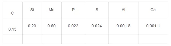
A certain steel mill employs silicon-manganese composite deoxidation in its continuous casting smelting process. Upon completion of refining, the total oxygen content in the molten steel is approximately 40×10⁻⁶ by mass fraction. Calcium treatment is not performed during the refining process. Specific compositions are detailed in Table 1.
During ladle pouring, abnormal erosion of the pouring rod frequently caused uncontrolled fluctuations in the crystallizer liquid level, leading to premature termination of pouring. Accident samples were obtained, revealing severe erosion in the lower control flow zone of the rod tip. Samples were taken from both the accident sample and the rod tip raw material for comparison.
1.1 XRF and XRD Analysis
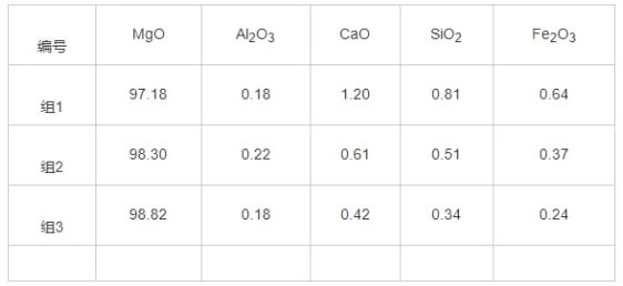
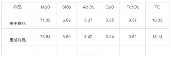
The chemical analysis results for the rod heads and raw materials are shown in Tables 3 and 4. The primary component of the rod head raw material is MgO, with a mass fraction exceeding 97%, along with trace amounts of calcium, silicon, iron, and aluminum oxides. The main constituents of the rod head material are MgO and graphite, with MgO accounting for 72%–75% by mass and carbon approximately 18% by mass. Both silicon and calcium content decreased to some extent before and after plug rod usage.
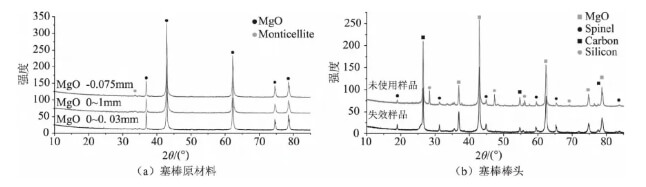
The phase analysis results for the rod tip material and raw material are shown in Figure 1. The raw material for the rod tip is high-purity magnesia, with the main crystalline phase being periclase and a small amount of calcic olivine impurity phase. The main crystalline phase of the rod tip material is periclase, containing graphite, metallic silicon, and a small amount of spinel.
1.2 Physical Indicator Analysis
The bulk density of the rammed material decreased from 2.60 g/cm³ before use to 2.48 g/cm³ after use, while the apparent porosity increased from 15.1% before use to 18.0% after use. This change resulted from the reaction of some antioxidant additives, the loss of low-melting-point binders at high temperatures, and the removal of carbonaceous components through reaction, collectively leading to increased apparent porosity and reduced bulk density.
1.3 Microstructural Analysis of the Steel-Refractory Interface
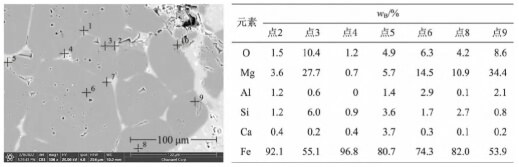
Sampling was conducted at different regions of the stopper rod tip, with specific sampling locations shown in Figure 2.
1) Positions 1 and 2: Erosion zone below the flow control point and boundary of the flow control point (outer arc surface);
2) Position 3: Non-molten metal contact zone of the stopper rod tip (inner arc surface);
3) Position 4: Uneroded zone above the flow control point (outer arc surface);
4) Position 5: Precipitated crystalline material region (inner arc surface).
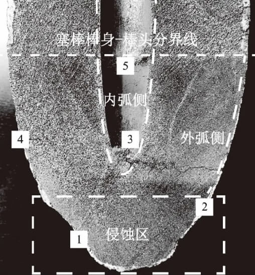
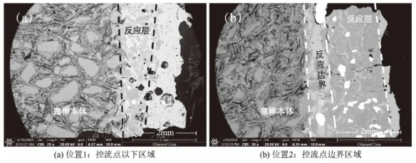
Figure 3 shows the morphology of the reaction layer between the stopper surface and molten steel. Positions 1 and 2 are located at the erosion front between molten steel and the MgO-C stopper. Their micro-area morphology and structure are fundamentally similar, consisting from outer to inner layers of: MgO decomposition reaction layer, reaction boundary layer, and unreacted MgO-C layer. Along the erosion front between molten steel and refractory material, MgO particle size fragmented from millimeter-scale to several micrometers to tens of micrometers. This process did not generate low-melting-point products. The removal of carbon components through reaction increases porosity, allowing varying degrees of molten steel penetration. At Position 2, the reaction layer is thicker, reaching 1.5–2 mm, with a less developed porous structure; whereas at Position 1, the reaction layer is relatively thin, only 300–500 μm thick. At Position 2, MgO decomposition is lower, resulting in a relatively dense reaction layer structure with strong bonding strength between the reaction layer and the base layer. In contrast, Position 1 exhibits higher porosity in the reaction layer, loose reaction boundaries, and poor bonding with the base layer. Additionally, due to the high flow velocity of molten steel below the flow control point, intense physical permeation, scouring, and erosion occur, causing the reaction layer to be eroded and carried away by the molten steel before it can fully develop.
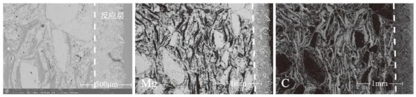
Position 3, located on the inner arc side of the stopper rod tip, did not contact molten steel and thus avoided wetting, erosion, or slag contamination. Figure 4 shows a microstructure and morphology similar to Positions 1 and 2, with the reaction layer primarily composed of fine MgO particles and a thickness of only 300–500 μm. Elemental scanning analysis indicates that graphite and other carbonaceous components have largely disappeared.
Position 4 is located above the flow control point, where the reaction layer and porosity structure are underdeveloped, with a thickness of 400–800 μm. Although the molten steel flow velocity remains relatively high above the flow control point, the formation of “negative pressure” has a significantly reduced impact, resulting in a comparatively weaker tendency for MgO decomposition.
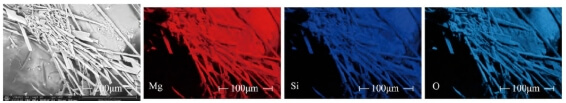
Position 5 is located within the inner arc of the rod head where molten steel has not yet contacted the area. Visible crystalline precipitates, distinct from the plug body itself, can be observed with lengths reaching the millimeter scale. Their morphology differs markedly from the internal composition particles of the plug head material. These precipitates form and develop along the thickness direction of the plug, creating dendritic white “crystalline whiskers.” Their composition consists of magnesium and silicate oxides, with morphological characteristics and elemental distribution shown in Figure 5.
2.Erosion Mechanism of MgO-C Plugs
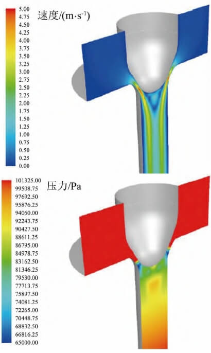
2.1 Analysis of Flow Control Zone Kinetic Conditions
The flow control point refers to the geometric tangency point between the multi-arc stopper rod and the arc-shaped submerged nozzle bowl at the closed position. The flow control region extends both above and below this point. Using the finite element method, the molten steel flow velocity and pressure distribution around the stopper rod were calculated under conditions of a ladle melt pool level of 1 m and a steel flow rate of 2.5 t/min, as shown in Figure 6. Below the control point, the molten steel flow velocity significantly increases, reaching a maximum of 5 m/s. Correspondingly, the pressure in this region drops sharply, forming a negative pressure zone. A systematic analysis of pressure variations along the centerline of the stopper rod, from the ladle melt pool surface to the outlet region of the crystallizer submerged nozzle, is presented in Figure 7. It can be observed that a high-vacuum negative pressure zone forms near the plug rod flow control point, particularly below it. Within this zone, the molten steel forms a high-velocity “jet” flow structure. The high-velocity flow and negative pressure erosion are key kinetic factors contributing to plug rod tip failure.
2.2 Vacuum Thermal Reduction Reaction of MgO-C
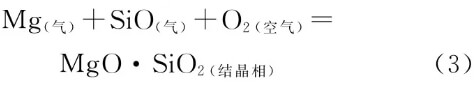
The reaction mechanism for the formation of the decarburization reaction layer and the decomposition of large MgO particles at the reaction interface is:
MgO (rod tip) + C (rod tip) = Mg (gas) + CO (gas) (1)
Reaction (1) is one of the primary factors in MgO decomposition. At steelmaking temperatures, this is mainly caused by the formation of a “negative pressure zone” in the controlled flow region [9,10]. Table 5 presents the thermodynamic conditions for reaction (1) [11]. The critical temperature for MgO reduction by carbon at atmospheric pressure is 1,876 °C. At 0.1 atm, the critical temperature drops to 1,559 °C. Under high vacuum conditions (1–100 Pa), the critical temperature ranges from 1,000 to 1,400 °C, significantly accelerating reaction (1).
Reaction between MgO and carbon components generates gaseous products like magnesium vapor, forming in-situ pores. This reduces material bulk density while increasing porosity, manifesting as large MgO grains fracturing along graphite distribution and the molten steel’s thermal interface. The result is a reactive layer with a porous, loose structure. This process occurs simultaneously along both the outer arc (in contact with molten steel) and inner arc (not in contact with molten steel) of the plug rod, though the reaction rate is significantly lower on the inner arc side. Along the outer arc, reaction intensity decreases sequentially from the rod tip toward the body at sampling positions 1, 2, and 4. Position 1 experiences the most severe impact and fastest erosion due to the combined effects of high vacuum and high-velocity molten steel flow.
Figure 8 shows two intermediate stages of MgO particle decomposition at the reaction boundary: Region 1 depicts the mechanism of reaction (1), where MgO grains undergo edge cracking and fragmentation near the reaction layer. Region 2 reveals a significant proportion of large MgO particles, ranging from tens to hundreds of micrometers in size, exhibiting substantial morphological and dimensional differences compared to Region 1.
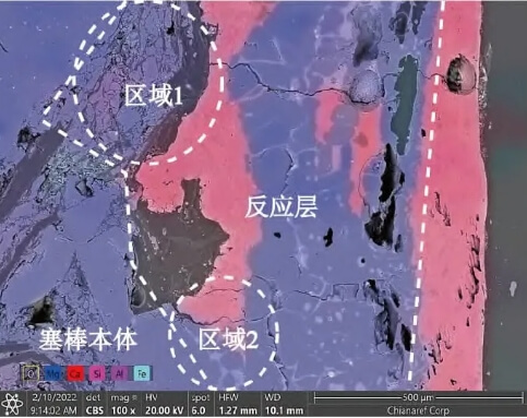
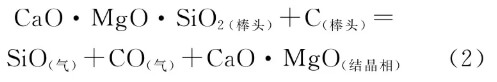
The formation of large particles in Zone 2 is related to the type of raw material used for the rod heads and the preparation process of the raw material. Calcium and silicon impurities in the magnesia raw material segregate and accumulate in the interstitial spaces of the periclase particles due to selective crystallization. Under high-temperature and vacuum conditions, if the silicon content in the matrix is high, reaction (2) occurs. In this process, the siliceous components are readily reduced [12], forming gaseous low-valent silicon oxides and high-melting-point crystalline phases. The crystalline structures are extremely small, only a few micrometers in size, and are accompanied by shrinkage cavities and cracks around the crystals, as shown in Figure 9.
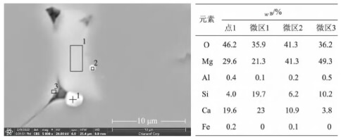
At high magnification, the intergranular matrix microstructure of MgO particles exhibits a mass percentage ratio of calcium, magnesium, and silicon components of approximately 1:1:1. This corresponds to a chemical composition of CaO·MgO·SiO₂ close to that of calcium-magnesium olivine (CaMgSiO₄). XRD analysis of the raw material also confirms the presence of this mineral phase. Within the precipitated crystals, the silicon mass fraction significantly decreased from approximately 20% to 4–6%. This process involved the escape of SiO in gaseous form from the intergranular regions into either the molten steel (outer arc) or the atmospheric environment (inner arc). Calcium-magnesium olivine has a melting point of 1390°C and inherently weakens grain boundary strength at steel pouring temperatures [14,15]. while the newly formed crystals act as pinning agents and disrupt the continuous grain boundary structure, causing MgO to flake off in large particles into the molten steel.
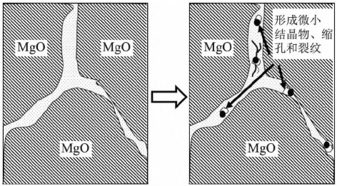
The high-melting-point crystals produced by reaction (2) precipitate from the silicon-rich matrix between MgO particles. The primary crystals are extremely fine, measuring only a few micrometers in size, and consist mainly of magnesium and calcium oxides. This process occurs as high-silicon oxides in the matrix are reduced and released as gases. The remaining system becomes supersaturated with magnesium and calcium, crystallizing as high-melting-point magnesium-calcium oxides. This crystallization causes volume contraction and creates “shrinkage cavities” near the original crystal sites, each only a few micrometers in diameter. However, the large number of these tiny cavities can coalesce into interconnected pores. Located near the reaction layer (as shown in Figure 10), these shrinkage cavities gradually form pathways for molten steel to infiltrate the refractory matrix. This severely degrades intergranular strength, ultimately causing cracks to propagate along grain boundaries that have been pinched and infiltrated by molten steel, resulting in the spalling of large MgO particles.
Dendritic precipitates were observed at position 5. Their formation mechanism relates to reactions (1) and (2), where magnesium vapor from reaction (1) and SiO gas from reaction (2) diffuse through channels formed by the material’s own pores and reaction pores, passing through the reaction layer into the external vacuum environment. The outer arc section contacts high-temperature molten steel, supplying magnesium, silicon, and oxygenation to the molten steel. The actual vacuum level in the inner arc region is significantly lower than that in the lower part of the flow control zone. Moreover, the gas gap within the plug rod’s inner cavity constitutes a “semi-oxygen-rich” environment. Consequently, the magnesium vapor and SiO gas react with oxygen in the air (Reaction 3) to form MgO·SiO₂. Since the development of primary crystals along the oxygen potential gradient exhibits selectivity and directionality, this process results in the formation of “dendritic” white whiskers oriented along the thickness of the plug rod.
Reactions (2) and (3) demonstrate that newly formed crystalline structures emerge both on the outer arc reaction boundary layer and the inner arc surface of the rod tip. While differing in chemical composition, physical morphology, and formation mechanisms, these structures are interconnected and mutually corroborative.
2.3 Erosion Mechanism of MgO-C Plugs
Figure 11 illustrates two failure mechanisms of MgO-C plugs under high vacuum and high temperature conditions. The “green box” indicates a micro-region of an MgO particle at the interface of the reaction layer at the leading edge of the erosion front. Figure 11a and Figure 11b depict the decomposition failure process of MgO particles under the dominant influence of Reaction (1) and Reaction (2), respectively.
1) Figure 11a depicts the stepwise decomposition and fragmentation of MgO grains into minute particles along the high-temperature thermal interface formed by molten steel, driven by reaction (1) under high-vacuum conditions;
2) Figure 11b illustrates the process where reaction (2) causes MgO grain boundaries to become “embrittled” and crack due to pinning, leading to the exfoliation of large-sized grains.
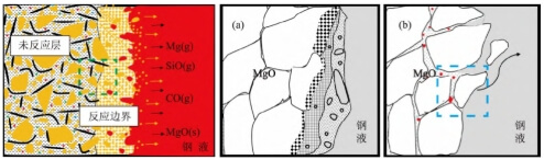
The process within the “blue box” micro-region in Figure 11b is shown in Figure 12. In the matrix zone, fine crystallites rich in magnesium and calcium form, accompanied by shrinkage cavities and cracks developing in situ nearby. These ultimately constitute pinning defects that weaken MgO intergranular strength and create rapid pathways for molten steel to penetrate into the material matrix. The erosion of MgO-C rod heads results from the combined effects of mechanisms (1) and (2). Figure 11b illustrates greater direct harm to plug rod flow control failure and molten steel cleanliness. Although magnesium supply to molten steel in Figure 11a occurs at extremely trace levels, it warrants attention for steel grades like high-grade bearing steel that exhibit special sensitivity to molten steel magnesium content and inclusion types.
3.Hazards and Countermeasures
Continuous casting protection requirements mandate that associated refractory materials must not become secondary sources of contamination for molten steel, thereby compromising its cleanliness. For clean steel production, refractories must also avoid negatively impacting or modifying the endogenous inclusion system. Analysis of MgO-C stopper rod erosion and failure reveals primary hazards:
1) Production continuity and billet quality. Severe erosion of the MgO-C stopper tip leads to failure of continuous casting flow control and loss of control over the crystallizer liquid level, resulting in premature termination of continuous casting and other safety and quality risks.
2) Magnesium supply to molten steel. As shown in reaction (1), the eroded MgO-C rod tip can become a source of Mg in molten steel, causing excessive magnesium content. This poses a hazard for certain clean steels requiring strict control of magnesium-aluminum spinel-type inclusions.
3) Formation of high-melting-point macroscopic inclusions. Reaction (2) produces large MgO particles that directly contaminate molten steel. MgO is a brittle inclusion with high melting point, high elastic modulus, and low deformability, reaching tens of micrometers in size. Strict control and avoidance are essential.
4) Induction of surface defects in rolled products. Reaction (1) causes MgO to decompose into smaller MgO particles that do not readily float. Once enveloped by large liquid inclusions such as calcium aluminate, they form brittle cores. During rolling, these inclusions impair the plastic deformation capability of the steel matrix along the rolling direction, readily causing surface quality defects in rolled products.
The following measures can be adopted to prevent and mitigate the aforementioned effects.
1) Improve the flow dynamics in the flow control zone by optimizing the refractory shape design and layout around the ladle tapping hole, thereby reducing vacuum levels and molten steel flow velocity in the negative pressure zone to mitigate reaction conditions.
2) Select high-purity magnesia with well-developed MgO grains, large particle size, and high density. Enhance raw material purity, reduce impurity content, and control impurity types. Maintain a silicon mass fraction in the matrix below 3% and control the calcium-to-silicon ratio between 6 and 10 to reduce MgO cracking tendencies.
3) Select non-MgO-C materials with low saturated vapor pressure and relatively low susceptibility to negative pressure conditions to mitigate the tendency for carbon thermal reduction decomposition and fragmentation under vacuum and high-temperature environments.
Conclusion
For MgO-C plug rods, the rod tip material is prone to react under high-temperature and vacuum conditions, leading to abnormal material behavior.
1) Reaction with carbon components causes MgO particles to decompose and fragment, forming a reaction layer dominated by fine particles and high porosity. This layer erodes beneath the flow control point under molten steel erosion.
2) High silicon content in raw material impurities, present as calcium-magnesium olivine phase, can precipitate high-melting-point crystals. These form in-situ shrinkage cavities, creating pathways for molten steel intrusion. This weakens intergranular bonding and ultimately causes large MgO particles to fracture.
3) Impact on molten steel cleanliness:
– Magnesium supply to the steel may affect clean steel grades sensitive to specific inclusion types; On the other hand, the direct formation of large macroscopic inclusions directly compromises molten steel cleanliness.
4) Measures to effectively reduce such plug erosion and flow control anomalies include: optimizing the flow field in the flow control zone to lower internal vacuum levels and molten steel flow velocity; enhancing the purity of raw material MgO while controlling the types and content of impurities in the intergranular matrix; and selecting non-MgO-C materials.