The stopper rod is a type of shaped refractory material utilized during the continuous casting process; it serves to maintain a stable liquid level within the mold, regulate the linear flow rate of the molten steel, and ensure both the surface and internal quality of the cast billet. In actual production, the stopper rod plays a pivotal role in ensuring the stability of steelmaking operations. Any issues arising with the stopper rod—such as erosion, breakage, or nozzle clogging—can result in excessive fluctuations in the molten steel level within the mold; in severe cases, this may necessitate the premature termination of the casting stream or force an emergency shutdown of the continuous casting machine.
1.Analysis of Stopper Rod Fracture
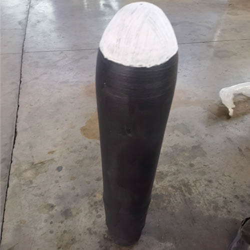
A certain steelworks’ slab continuous casting machine has frequently experienced issues involving stopper rod fractures during the casting process. This has severely disrupted the normal operation of the caster. Statistical analysis of these incidents reveals that 20% of the failures—specifically, the detachment of the stopper rod head—occur either during the tundish preheating phase or at the commencement of casting. The remaining failures occur during the actual casting process, manifesting either as the detachment of the stopper rod head or as a fracture of the rod at a position approximately 650–700 mm below the upper rim; the fracture surface typically exhibits a “V” shape (see Figure 1). Statistics for 2021 record a total of 12 stopper rod-related incidents—averaging one per month. Each incident resulted in an unplanned shutdown of the continuous casting machine, necessitating the re-preheating of the tundish, preparation of backup equipment, and the restarting of the casting process, thereby disrupting the normal production schedule. Consequently, there is an urgent need to resolve these stopper rod issues in order to stabilize continuous casting operations and mitigate financial losses.
A statistical classification of stopper rod accidents was conducted, identifying thermal shock, material strength, and issues related to the design and installation of the stopper rod as the primary factors contributing to stopper rod fracture and the detachment of the stopper head.
1.1 Thermal Shock Issues
Based on an analysis of the materials used for the stopper body and head, as well as the stopper’s manufacturing process, it is concluded that the materials currently employed meet the required process specifications. Since the steelworks primarily produces carbon structural steel, high-carbon steel, and certain medium-carbon alloy steels, the erosive impact on the stopper is minimal. Furthermore, the stopper design does not feature a distinct slag line, and the scouring of the stopper head is not severe; even after 15 hours of continuous casting under normal conditions, the stopper head maintains excellent flow control and exhibits uniform erosion. Consequently, the material design is deemed fundamentally sound. An examination of the fracture surface—located at a position 50–60 mm from the tip and characterized by a clean, flat break—indicates that the primary issue lies in the manufacturing stage. It is imperative to adjust and reinforce the production process, as the direct cause of the stopper’s fracture was the internal stress induced by compositional non-uniformity in the raw materials used for its manufacture.
Monitoring of the tundish preheating process at the site revealed an issue of low heating efficiency. The tundish preheating utilizes converter gas, which typically has a calorific value of 1300 × 4.1868 kJ/m³. The preheating duration is 3 hours, during which the stopper rod remains in the open position and the temperature reaches 1000°C; furthermore, the tundish is not sealed during preheating, resulting in severe flame spillage. Poor preheating of the stopper rod leads to uneven thermal stress within its refractory material, thereby generating micro-cracks. During the casting process, the stopper rod operates in an extreme environment, where any minor defect can be significantly amplified.
1.2 Strength Issues
Fractures in the slag-line region of the stopper rod typically occur during specific operational phases—specifically, within the first one or two heats following a nozzle change, after the bonding material has fully cured, or during the tundish rapid-exchange process. Analysis indicates that these cracks—and subsequent fractures—arise when the stopper rod is actuated to close during the steel casting process, subjecting it to combined lateral and longitudinal forces.
An assessment of the stopper rod body’s structural integrity reveals that its strength is relatively low under high-temperature conditions. Consequently, the rod becomes susceptible to fracture when subjected to the erosive action of molten steel or mechanical stress; therefore, it is necessary to reinforce the structural strength of the stopper rod body.
1.3 Stopper Rod Design and Installation
A follow-up analysis of the on-site stopper rod installation revealed the following issues: ① Design flaws in the stopper rod. When the casting stopper rod is in the open position, it extends 200 mm above the tundish cover; however, according to standard design specifications, an extension of 50 mm is sufficient. The excessive length of the stopper rod subjects it to immense external forces during emergency closure operations, making it prone to fracture—particularly at the slag line, where the rod’s diameter changes and the structure is inherently weaker. ② Issues regarding the installation of the stopper rod. The primary problem stems from the fact that the stopper rod is installed offline; consequently, the rod may sustain damage due to vibration or jarring during the process of transferring the tundish to the casting line. Furthermore, the installation procedure requires a specific “toe-in” alignment; the presence of this “toe-in” creates lateral forces when the stopper rod is closed, leading to the formation of cracks in the stopper head or other structurally weak points along the rod. Additionally, during the casting process, when operators switch from automatic to manual mode to close the stopper rod—applying significant physical force to depress the operating lever—this action further exacerbates the damage to the rod.
2.Improvement Measures
2.1 Improvement of the Stopper Rod Fracture Issue
To address the aforementioned issues, improvements to the currently utilized stopper rods have been proposed, with the specific plan outlined as follows: (1) While ensuring that production requirements are met, the material composition will undergo fine-tuning to appropriately enhance the stopper rod’s thermal shock resistance, concurrently strengthening the neck section of the rod. The underlying strategy involves incorporating fine SiC powder into the batch mix for the tundish stopper rods—specifically targeting the rod head and the slag line zone—and adopting a composite structural design. This approach aims to improve the overall mechanical properties of the stopper rod while simultaneously reducing its coefficient of linear expansion. When 5% fine SiC powder is added, the room-temperature and high-temperature flexural strengths of the magnesia-carbon rod-head material reach 8.2 MPa and 9.4 MPa, respectively; the average coefficient of linear expansion is 7.1 × 10⁻⁶/°C; and no significant cracks were observed after three thermal shock cycles at 1100°C. (2) Adjustment of stopper rod length. The stopper rods currently in use are excessively long—reaching 1750 mm—which not only increases the difficulty of manufacturing but also amplifies the lateral forces generated by the flow of molten steel during operation, thereby increasing the risk of rod fracture under stress. Based on on-site operational conditions, the length of the stopper rods will be adjusted to 1650 mm. (3) Optimization of the stopper rod head. The shape of the stopper rod head will be changed from spherical to conical to enhance the precision of flow control; concurrently, the diameter of the rod head section will be reduced from 60 mm to 45 mm.
2.2 Improvement of Stopper Rod Installation Method
Currently, the stopper rod is installed within the tundish repair area; however, the vibrations generated during the transport of the tundish can have an adverse effect on the stopper rod. To address this, the existing installation procedure should be improved by shifting from an “offline” method to an “inline” installation performed prior to tundish preheating, thereby minimizing the impact of the transport process. Furthermore, before commissioning the stopper rod, the actuator beam must be thoroughly inspected for any signs of deformation, and the stopper rod itself checked for straightness. During installation and commissioning, the practice of “tip-biting” (misalignment causing the rod tip to catch) must be eliminated, and strict centering maintained to prevent the stopper rod from being subjected to lateral forces—which could lead to fracture—while regulating the flow.
2.3 Optimization of Stopper Rod Baking Schedule
The stopper rod preheating schedule was optimized to address issues related to thermal shock. During off-line preparation, the tundish lid is securely seated to seal the rim; a rigorous seal is maintained prior to preheating to enhance the overall effectiveness of the tundish preheating process. At the commencement of tundish preheating, the stopper rod remains in the closed position; the rod is opened only after the tundish has undergone preheating for 30 minutes, thereby facilitating the effective preheating of both the stopper rod and the upper nozzle. The tundish preheating protocol was revised to stipulate appropriate preheating durations, as prolonged heating can shorten the service life of the tundish—potentially rendering it unusable. Furthermore, the heating flame must not be interrupted during the preheating process; should an interruption occur, the tundish in question must be discarded. Finally, the opening of the gas valve is strictly controlled in accordance with the prescribed tundish preheating temperature curve to ensure that the temperature rises to above 1000°C within the first 1 to 2 hours of the heating cycle.
2.4 Improving Stopper Rod Operations during Tap-Opening and Steel Casting
To address the customary practice of “rod-checking” (visual inspection of the stopper rod) during the tundish preheating process, the procedure has been revised: the preheating is now halted prior to the start of casting specifically for the purpose of inspecting the stopper rod. If any minor misalignment of the stopper rod is detected, it is fine-tuned at that stage; this minimizes the adverse effects—such as thermal shock and mechanical stress—that would otherwise result from interrupting the preheating and making forceful adjustments to the stopper rod during the actual preheating cycle.
During operations involving nozzle replacement, refractory bonding restoration, or rapid tundish exchange, the control mode is first switched from “Automatic” to “Manual.” The operator then manually supports the stopper rod lever, allowing the stopper rod to descend and close under its own weight; subsequently, the operator applies downward pressure to the lever to ensure the stopper rod is fully seated and securely closed before proceeding with the subsequent operational steps.
Implementation Process and Results
The aforementioned measures were implemented in two stages: First, the tundish preheating regimen was improved, tundish sealing was reinforced, and the effectiveness of stopper rod preheating was enhanced; concurrently, the procedures for stopper rod installation and operation were refined. Second, the stopper rods themselves were optimized; the manufacturer designed revised blueprints for the rods, proceeded with the fabrication of molds and rods, and—once conditions were met—conducted field trials.
During the field trials involving the improved stopper rods, the preheating, casting start-up, and steel casting processes were closely monitored. A protocol was established requiring that the stopper rod be hoisted out of the tundish during every scheduled machine shutdown. The steel grades cast during these trials included Q235, Q345, 45#, 50#, and others. Observations revealed that the condition of the stopper rod heads remained sound, flow control was effective, and the wear on the rod heads was uniform.
The implementation of these measures yielded tangible results: incidents of continuous caster downtime caused by stopper rod fractures gradually declined. In 2022, the steelworks recorded only two incidents of stopper rod fracture—a reduction of ten incidents compared to 2021—indicating that the performance and utilization of the stopper rods have stabilized.
In conclusion
By controlling the trace additives introduced during the stopper rod manufacturing process and optimizing the rod’s geometry, it is possible to enhance the stopper rod’s thermal stability and flow control precision. This contributes to stabilizing the mold liquid level, reducing the frequency of stopper rod opening and closing operations, and ultimately improving the overall performance of the stopper rod.
Through improvements and optimizations in the on-site installation, preheating, and operational procedures of the stopper rods, instances of fracture—caused by thermal shock or mechanical damage—have been significantly reduced, thereby bringing greater stability to the use of stopper rods within the tundish.